|
| ||
|
A propeller accelerates a large volume of air by a small amount |
A jet engine accelerates a small volume of air by a large amount |
The main function of any aeroplane propulsion system is to provide a force to overcome the aircraft drag, this force is called thrust. Both propeller driven aircraft and jet engines derive their thrust from accelerating a stream of air - the main difference between the two is the amount of air accelerated. A propeller accelerates a large volume of air by a small amount, whereas a jet engine accelerates a small volume of air by a large amount. This can be understood by Newton's 2nd law of motion which is summarized by the equation F=ma (force = mass x acceleration). Basically the force or thrust (F) is created by accelerating the mass of air (m) by the acceleration (a).
|
| ||
|
A propeller accelerates a large volume of air by a small amount |
A jet engine accelerates a small volume of air by a large amount |
Given that thrust is proportional to airflow rate and that engines must be designed to give large thrust per unit engine size, it follows that the jet engine designer will generally attempt to maximize the airflow per unit size of the engine. This means maximizing the speed at which the air can enter the engine, and the fraction of the inlet area that can be devoted to airflow. Gas turbine engines are generally far superior to piston engines in these respects, therefore piston-type jet engines have not been developed.
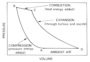 |
|
The operation cycle of a gas turbine |
The gas turbine engine is essentially a heat engine using air as a working fluid to provide thrust. To achieve this, the air passing through the engine has to be accelerated; this means that the velocity or kinetic energy of the air must be increased. First, the pressure energy is raised, followed by the addition of heat energy, before final conversion back to kinetic energy in the form of a high velocity jet.
The basic mechanical arrangement of a gas turbine is relatively
simple. It consists of only four parts:
1. The compressor
which is used to increase the pressure (and temperature) of the inlet air.
2. One or a number of
combustion
chambers in which fuel is injected into the high-pressure air as a fine
spray, and burned, thereby heating the air. The pressure remains (nearly)
constant during combustion, but as the temperature rises, each kilogram of hot
air needs to occupy a larger volume than it did when cold and therefore expands
through the turbine.
3.
The turbine
which converts some of this temperature rise to rotational energy. This energy
is used to drive the compressor.
4. The exhaust
nozzle which accelerates the air using the remainder of the energy added in
the combustor, producing a high velocity jet exhaust.
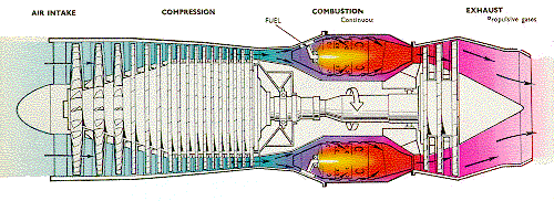 |
|
A schematic of a
gas-turbine engine
(turbojet) |
This generalization, however, does not extend to the detailed design of the engine components, where account has to be taken of the high operating temperatures of the combustion chambers and turbine; the effects of varying flows across the compressor and turbine blades; and the design of the exhaust system through which the gases are ejected to form the propulsive jet.
The centrifugal flow compressor employs an impeller to accelerate the air and a diffuser to produce the required pressure rise. Flow exit's a centrifugal compressor radially (at 90° to the flight direction) and it must therefore be redirected back towards the combustion chamber, resulting in a drop in efficiency. The axial flow compressor employs alternate rows of rotating (rotor) blades, to accelerate the air, and stationary (stator) vanes ,to diffuse the air, until the required pressure rise is obtained.
| |
|
A centrifugal impeller |
| |
|
An axial flow compressor (stators
omitted for clarity). This is the high pressure compressor from a General
Electric F404 engine |
An engine design using a centrifugal
compressor will generally have a larger frontal area than one using a axial
compressor. This is partly a consequence of the design of a centrifugal
impeller, and partly a result of the need for the diffuser to redirect the flow
back towards the combustion chamber. As the axial compressor needs more stages
than a centrifugal compressor for the equivalent pressure rise, an engine
designed with an axial compressor will be longer and thinner than one designed
using a centrifugal compressor. This, plus the ability to increase the overall
pressure ratio in an axial compressor by the addition of extra stages, has led
to the use of axial compressors in most engine designs, however, the centrifugal
compressor is still favored for smaller engines where it's simplicity,
ruggedness and ease of manufacture outweigh any other
disadvantages.
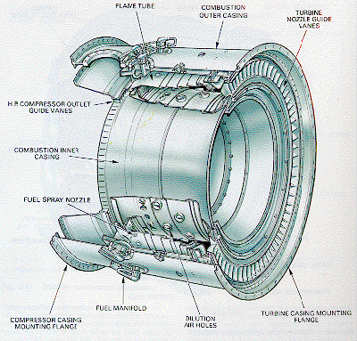
The combustion chamber has the difficult task of burning large quantities of fuel, supplied through fuel spray nozzles, with extensive volumes of air, supplied by the compressor, and releasing the resulting heat in such a manner that the air is expanded and accelerated to give a smooth stream of uniformly heated gas. This task must be accomplished with the minimum loss in pressure and with the maximum heat release within the limited space available.
The amount of fuel added to the air will depend upon the temperature rise required. However, the maximum temperature is limited to within the range of 850 to 1700 °C by the materials from which the turbine blades and nozzles are made. The air has already been heated to between 200 and 550 °C by the work done in the compressor, giving a temperature rise requirement of 650 to 1150 °C from the combustion process. Since the gas temperature determines the engine thrust, the combustion chamber must be capable of maintaining stable and efficient combustion over a wide range of engine operating conditions.
The temperature of the gas after combustion is about 1800 to 2000 °C, which is far too hot for entry to the nozzle guide vanes of the turbine. The air not used for combustion, which amounts to about 60 percent of the total airflow, is therefore introduced progressively into the flame tube. Approximately one third of this gas is used to lower the temperature inside the combustor; the remainder is used for cooling the walls of the flame tube.
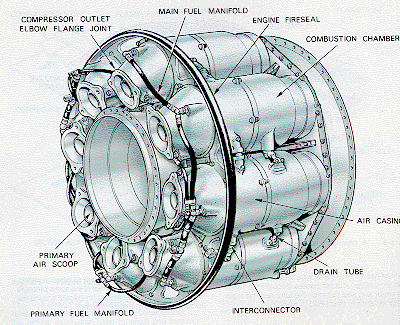
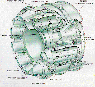
There are three main types of combustion chamber in use for gas turbine engines. These are the the multiple chamber, the can-annular chamber and the annular chamber.
This type of combustion chamber is used on centrifugal compressor engines and the earlier types of axial flow compressor engines. It is a direct development of the early type of Whittle engine combustion chamber. Chambers are disposed radially around the engine and compressor delivery air is directed by ducts into the individual chambers. Each chamber has an inner flame tube around which there is an air casing. The separate flame tubes are all interconnected. This allows each tube to operate at the same pressure and also allows combustion to propagate around the flame tubes during engine starting.
 |
|
|
 |
|
|
 |
|
|
 |
|
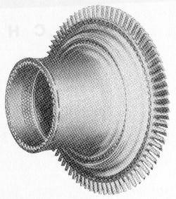
A high-pressure turbine
stage from a CFM56 turbofan
engine |
The turbine has the task of providing power to drive the compressor and accessories. It does this by extracting energy from the hot gases released from the combustion system and expanding them to a lower pressure and temperature. The continuous flow of gas to which the turbine is exposed may enter the turbine at a temperature between 850 and 1700 °C which is far above the melting point of current materials technology.
 |
|
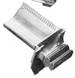
A turbine blade with cooling holes |
To produce the driving torque, the turbine may consist of several stages, each employing one row of stationary guide vanes, and one row of moving blades. The number of stages depends on the relationship between the power required from the gas flow, the rotational speed at which it must be produced, and the diameter of turbine permitted. The design of the nozzle guide vanes and turbine blade passages is broadly based on aerodynamic considerations, and to obtain optimum efficiency, compatible with compressor and combustor design, the nozzle guide vanes and turbine blades are of a basic aerofoil shape.
The desire to produce a high engine efficiency demands a high
turbine inlet temperature, but this causes problems as the turbine blades would
be required to perform and survive long operating periods at temperatures above
their melting point. These blades, while glowing red-hot, must be strong enough
to carry the centrifugal loads due to rotation at high
speed.
To operate under these conditions, cool air is
forced out of many small holes in the blade. This air remains close to the
blade, preventing it from melting, but not detracting significantly from the
engine's overall performance. Nickel alloys are used to construct the turbine
blades and the nozzle guide vanes because these materials demonstrate good
properties at high temperatures.
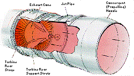
Gas turbine engines for aircraft have an exhaust system which passes the turbine discharge gases to atmosphere at a velocity in the required direction, to provide the necessary thrust. The design of the exhaust system, therefore, exerts a considerable influence on the performance of the engine. The cross sectional areas of the jet pipe and propelling or outlet nozzle affect turbine entry temperature, the mass flow rate, and the velocity and pressure of the exhaust jet.
A basic exhaust system function is to form the correct outlet area and to prevent heat conduction to the rest of the aircraft. The use of a thrust reverser (to help slow the aircraft on landing), a noise suppresser (to quieten the noisy exhaust jet) or a variable area outlet (to improve the efficiency of the engine over a wider range of operating conditions) produces a more complex exhaust system.
|
|
|
A basic exhaust
system |
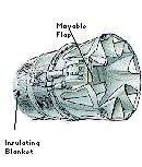
A more complex exhaust system with two
position nozzle and noise suppresser |
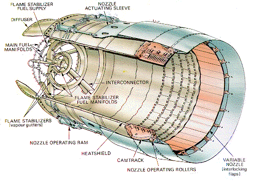
In addition to the basic components of a gas turbine engine, one other process is occasionally employed to increase the thrust of a given engine. Afterburning (or reheat) is a method of augmenting the basic thrust of an engine to improve the aircraft takeoff, climb and (for military aircraft) combat performance.
Afterburning consists of the introduction and burning of raw fuel between the engine turbine and the jet pipe propelling nozzle, utilizing the unburned oxygen in the exhaust gas to support combustion. The resultant increase in the temperature of the exhaust gas increases the velocity of the jet leaving the propelling nozzle and therefore increases the engine thrust. This increased thrust could be obtained by the use of a larger engine, but this would increase the weight, frontal area and overall fuel consumption. Afterburning provides the best method of thrust augmentation for short periods.
Afterburners are very inefficient as they require a disproportionate increase in fuel consumption for the extra thrust they produce. Afterburning is used in cases where fuel efficiency is not critical, such as when aircraft take off from short runways, and in combat, where a rapid increase in speed may occasionally be required.
 |
|
Typical afterburning jet pipe equipment |